Setting up the Prototype
Since the last update, I have made some fairly significant progress on the project. The three big breakthroughs are:
- Successfully applying the clincher connectors for the force-sensitive resistors
- Figuring out how to setup the connections for the FSR wire (the wire from the tactile pad to the enclosure)
- Getting the pressure pad to reliably detect people
The FSRs require the use of some sort of connector to be able to reliably connect wires to the flexible polymer of the FSR. I elected to use Amphenol FCI clincher connectors which are design for use with the FSRs we purchased. Applying the connectors to the FSRs is a delicate task, since it is very easy to break the connectors if they are clinched improperly. With guidance from a SparkFun guide on how to properly attach the connectors, I was able to apply all the connectors successfully. This was important since with COVID affecting shipping times, we did not have much time to get new parts in case we broke too many (I had purchased two spare connectors).
The clincher connectors facilitate the connection between the FSRs, and the wire going to the enclosure. Since the long wire (pictured below) has stranded wires which are hard to plug into standard headers (on the microcontroller and the clincher connectors), we need a small amount of solid core wire which is connected between the stranded wire and the aforementioned headers. Late one evening, I had an “a-ha!” moment where I realized it would be easiest to connect these wires using some quick-connects. Doing this would make it easier to transport the system, since it is quite bulky if we want to move it around.
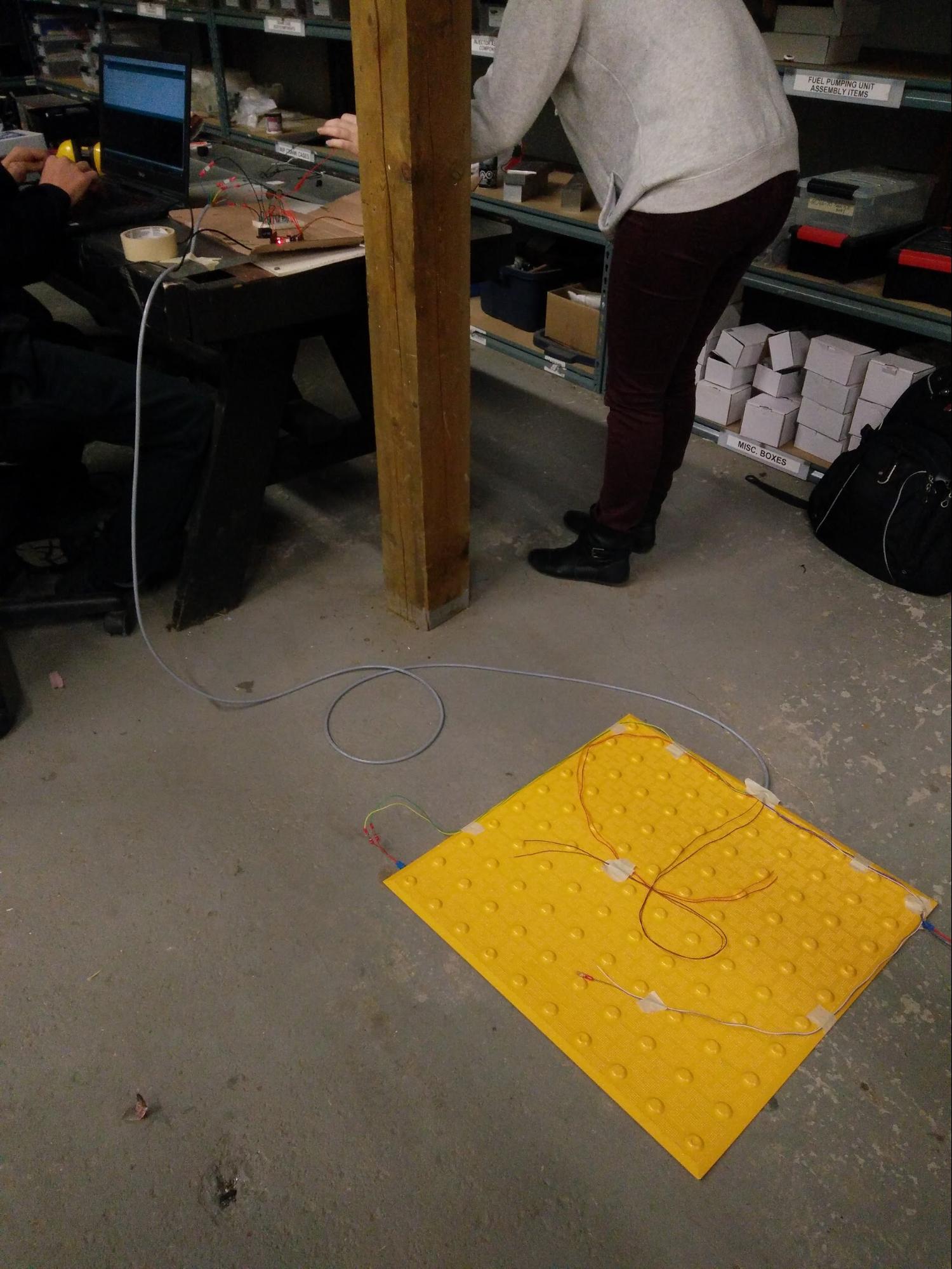
After completing the previous two items, we were ready to connect the FSRs to the tactile pad (shown in the picture above) and test out the pedestrian detection. The tactile pad presents some unique challenges since it is not designed for our application. Typically, the tactile pad would be drilled into the concrete. For our purposes, we are unable to drill it into concrete, since we do not have a “test strip” of concrete which we can deface for our demonstration. This is a dilemma since the tactile pad is slightly warped, so it does not lie perfectly flush to the ground. We observed that the FSRs could not detect the presence of a pedestrian unless they were standing very near to where the resistors are placed. Our solution was to make a quick visit to Home Depot to purchase some self-adhesive vinyl surface pads similar to what is shown below:

We applied these pads to the FSRs such that the FSRs are sandwiched between the vinyl pad and the tactile pad. Initial tests showed that this added some “preload” to the resistors. To compensate for this Sean increased the voltage reading required to indicate a pedestrian is standing on the tactile pad. After making these adjustments, the tactile pad worked amazingly well for detecting if someone was standing anywhere on it.
All that remains to be done is finish up the system and add some weather-proofing elements, and that will be detailed in my next update.