Connecting the Components
Since my last post I have soldered all the resistors to wires, and stripped the wires for the FSR pressure sensors. An unfortunate realization that I came to is that I should have also ordered heat shrink to protect the connection after soldering. My solution was to use some electrical tape to cover the soldered connections. This was not the perfect solution, but it should suffice for this project. A photo showing the resistor soldered to the buzzer is included below. Due to the unique circumstances with COVID-19, I actually prepared duplicates of everything. One set is for Sean to test his code with, and the other set is for Taylor so she can add appropriately sized holes and standoffs for the components in the enclosure.
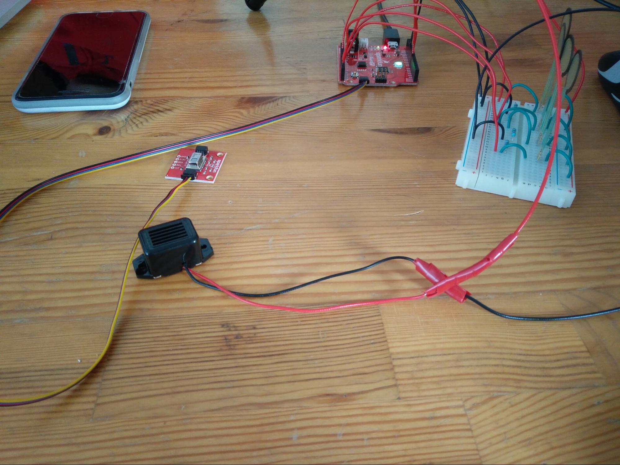
I made a trip out to Waterloo to meet with Sean and Taylor to bring them the components and perform some initial testing. We discovered that the buzzer did not want to work with the resistor I had selected for it. I’m not sure why this is, but luckily removing the resistor resulted in a normally functioning buzzer.
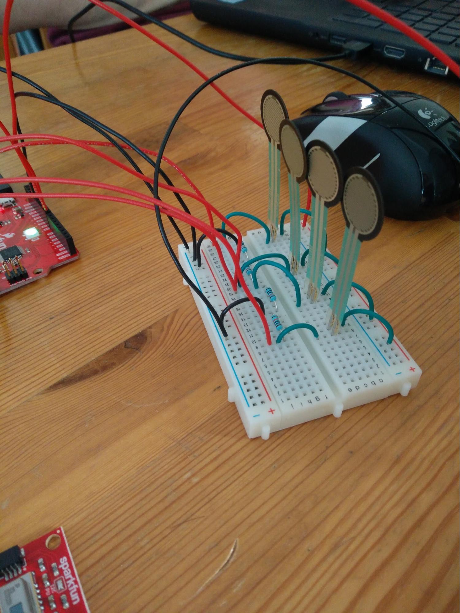
During the testing we also discovered the FSRs (pictured below) are very responsive when we squeezed them. Hopefully they will work similarly well when they are installed on the tactile pad.